
Since my last post I fabricated the battery packs, prepared the car for them, installed the packs, and ran the HV wires and BMS. The car is now almost ready for the first charge. Before then, I have to ensure that my settings for the motor controller are correct, plumb the water cooling for the batteries, and just generally frisk the car for mis-wires and possible shorts. When ripping and tearing on the frame, a lot of metal debris was generated. I can find it almost everywhere in the car, and perhaps I should blow down the motor too. Anyway, here are some specific details:
Battery pack fabrication
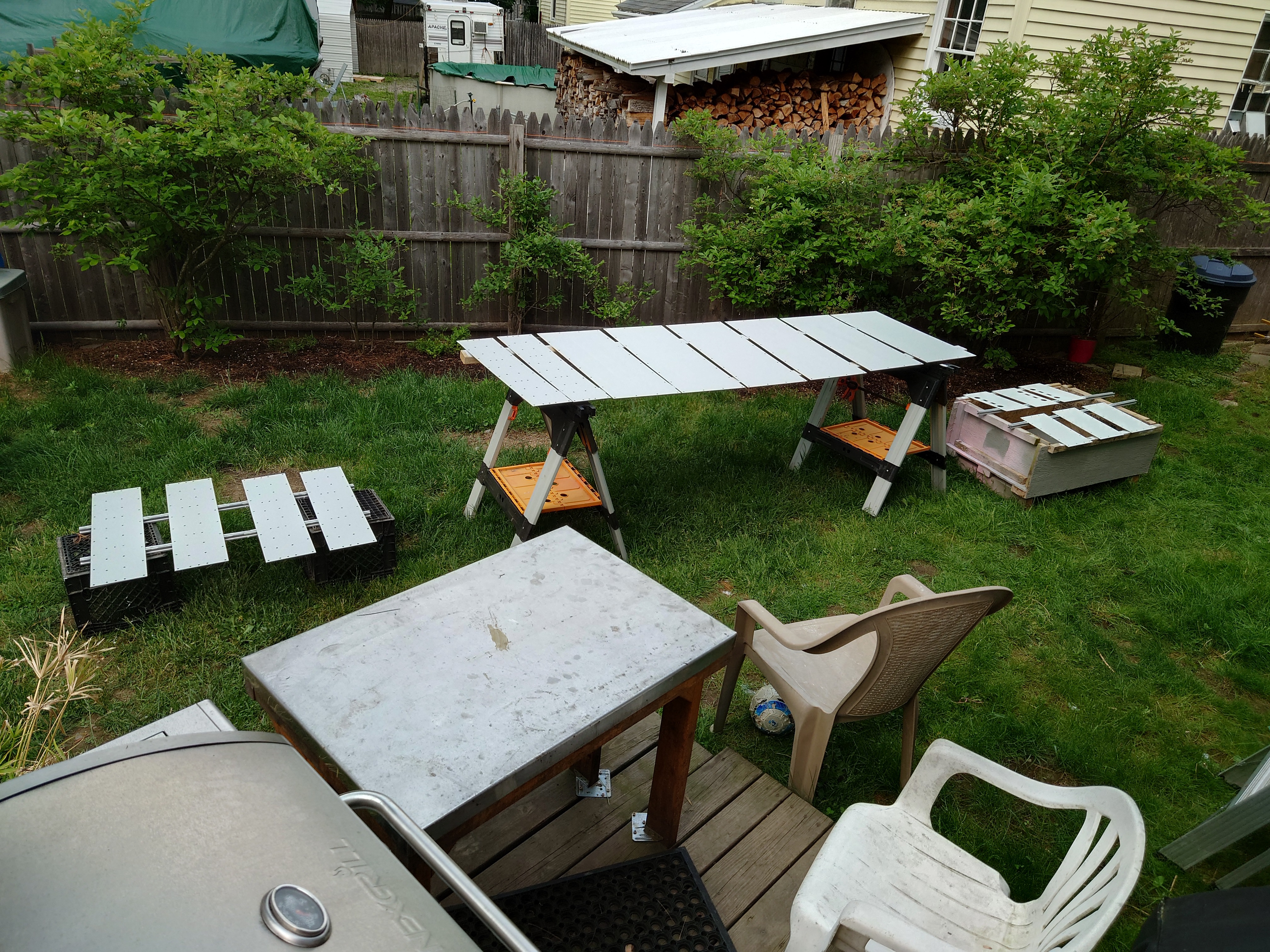
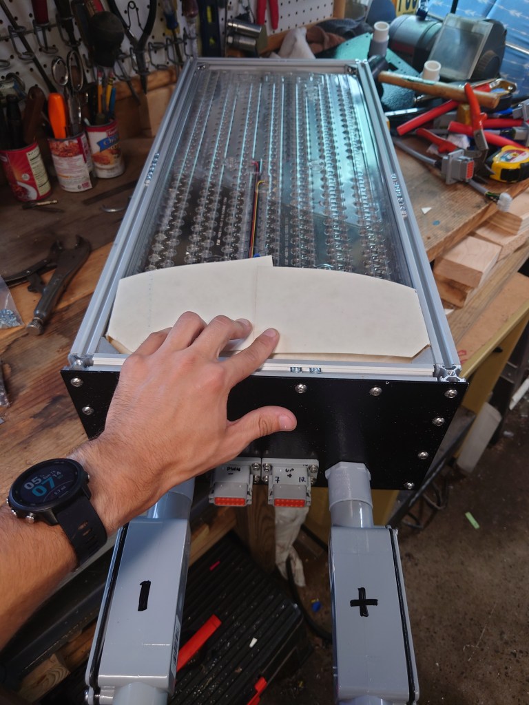
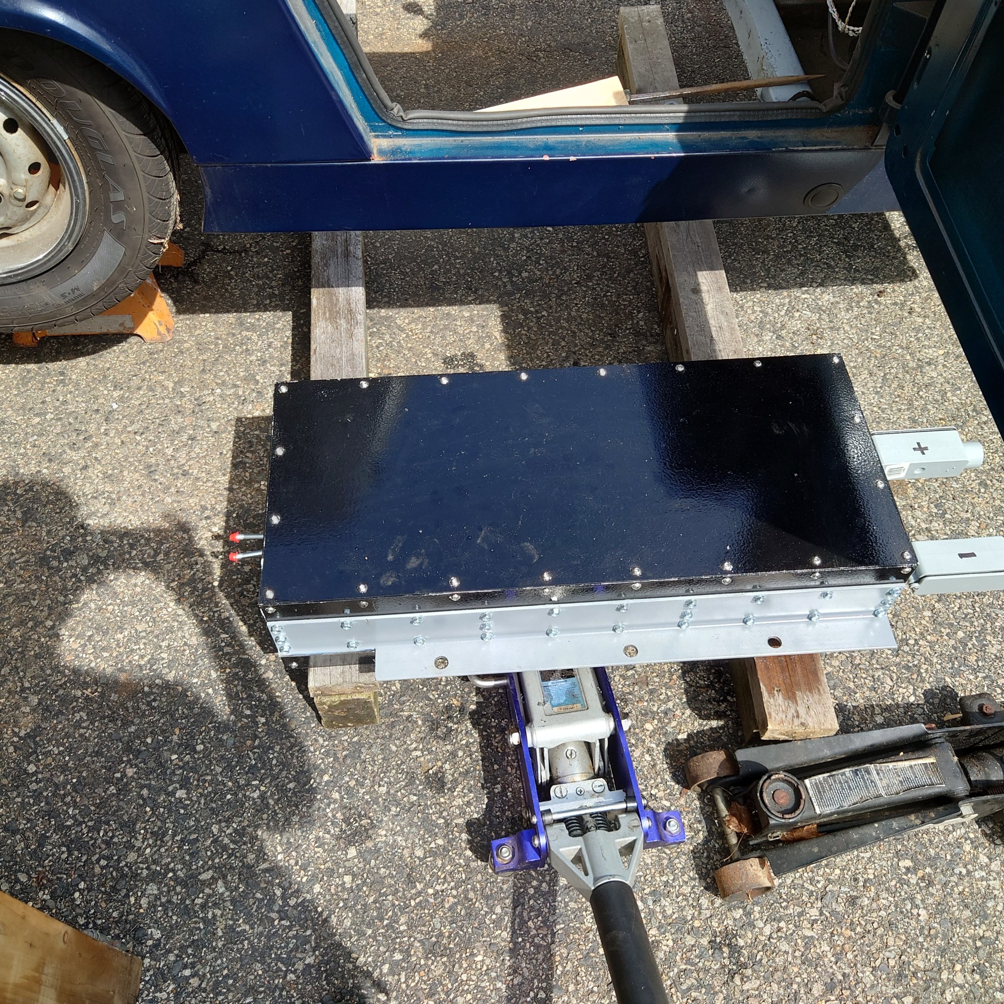
The battery packs were mocked up, as discussed in my previous post, and were ready to be fabricated. I cut aluminum extrusion and ordered steel side panels to be lasercut. This is a budget build, and I don’t expect to be cruising the freeway or hitting the track, so the material was acceptable in my opinion. The battery boxes as constructed are rigid, and I’m confident in their ability to perform their expected mission.
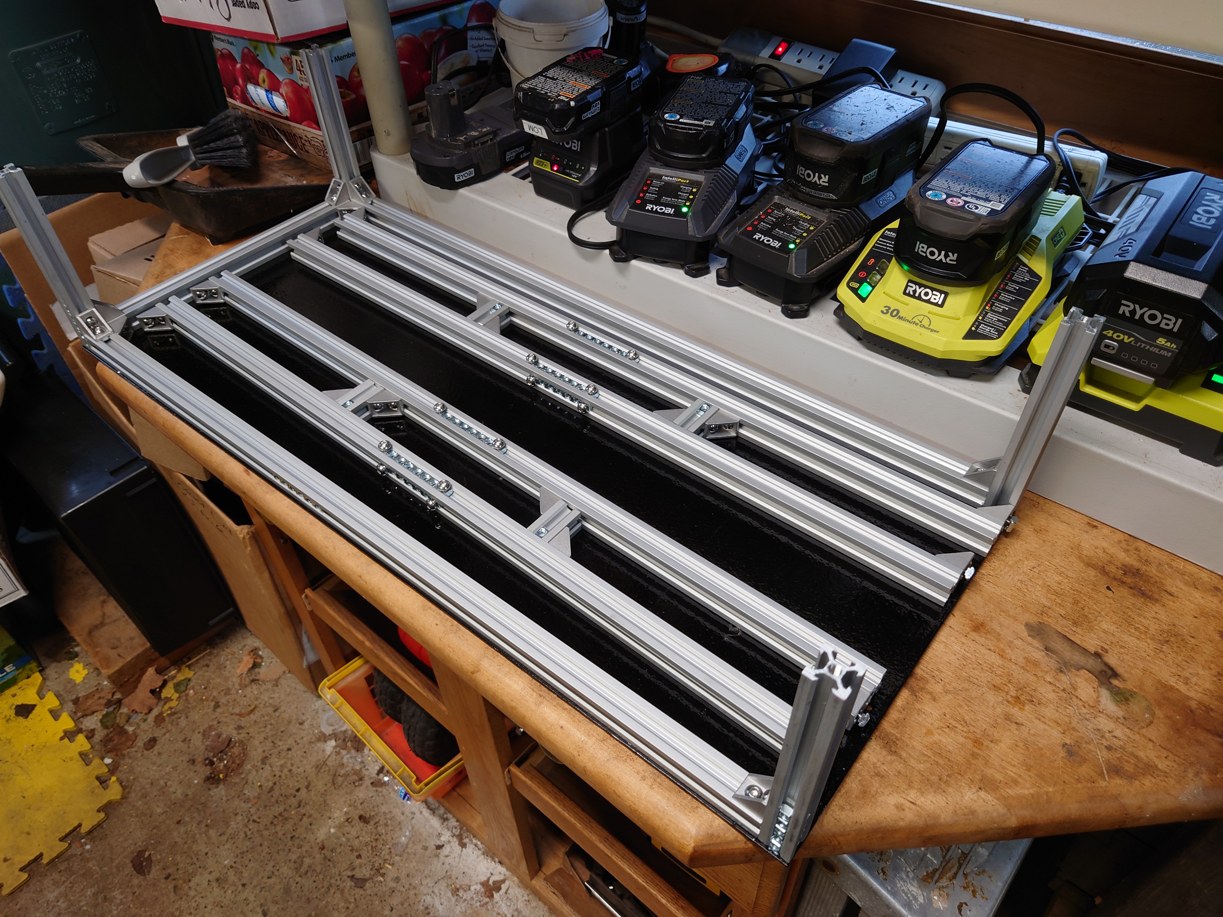
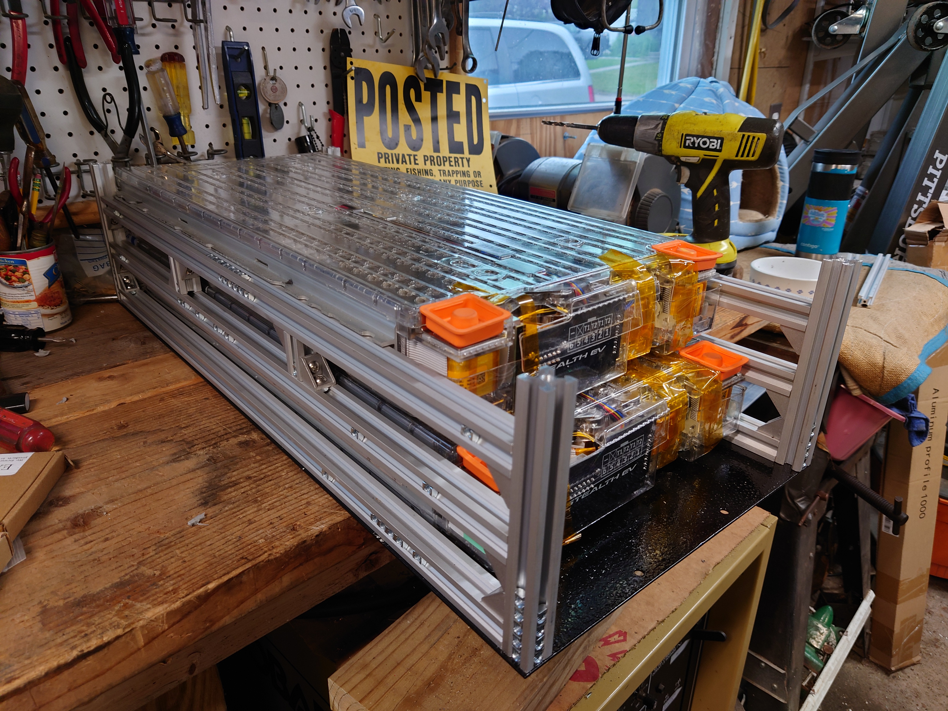
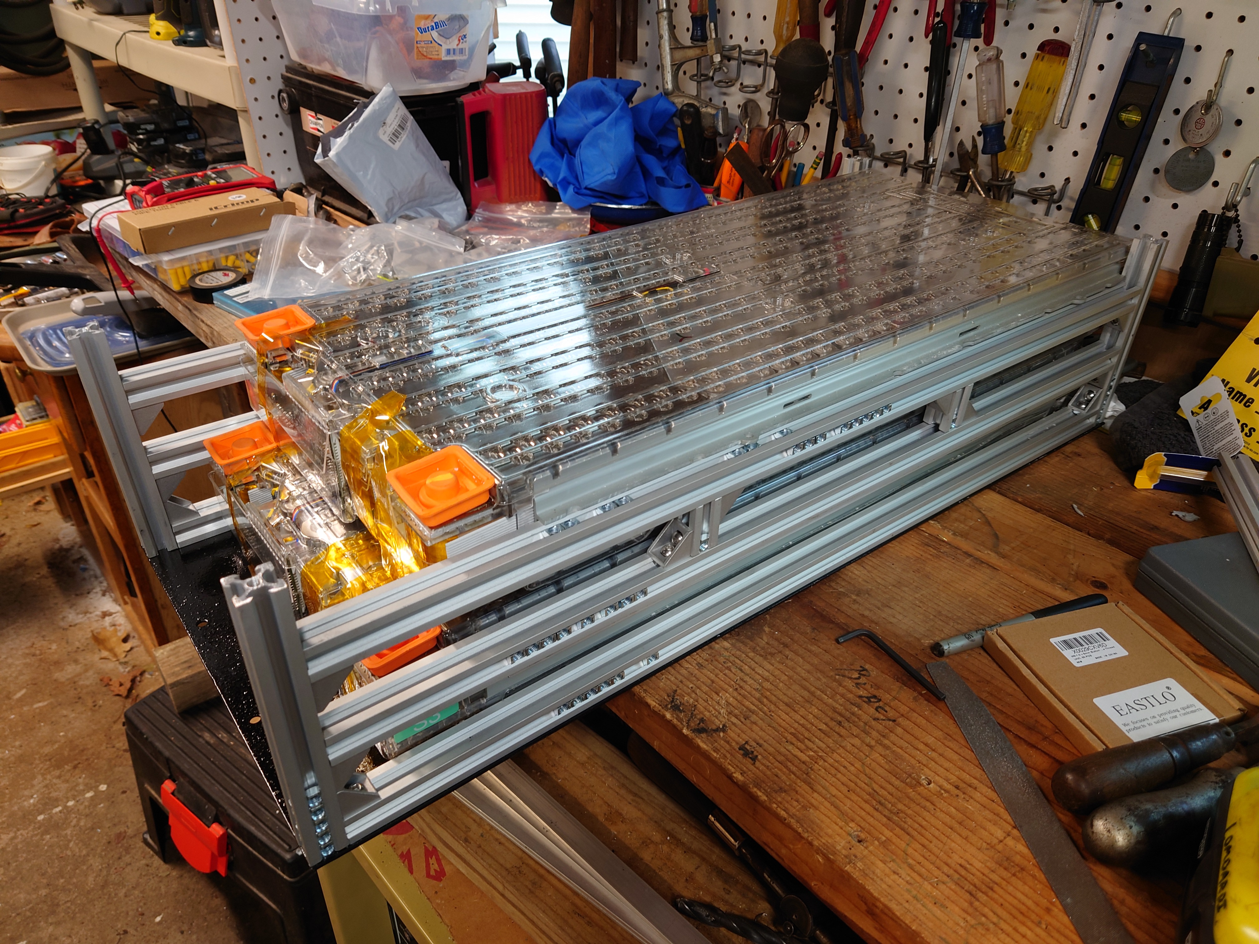


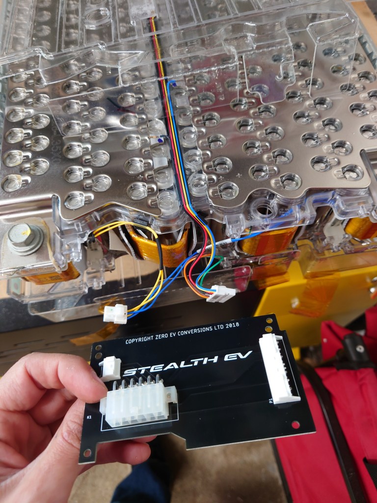
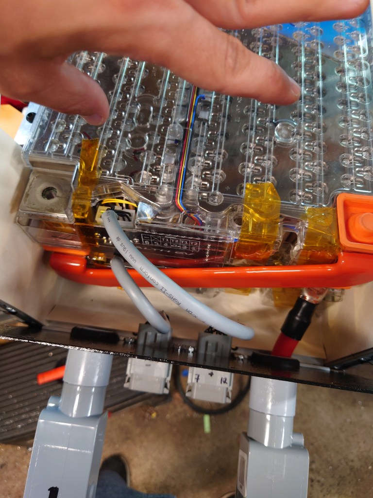
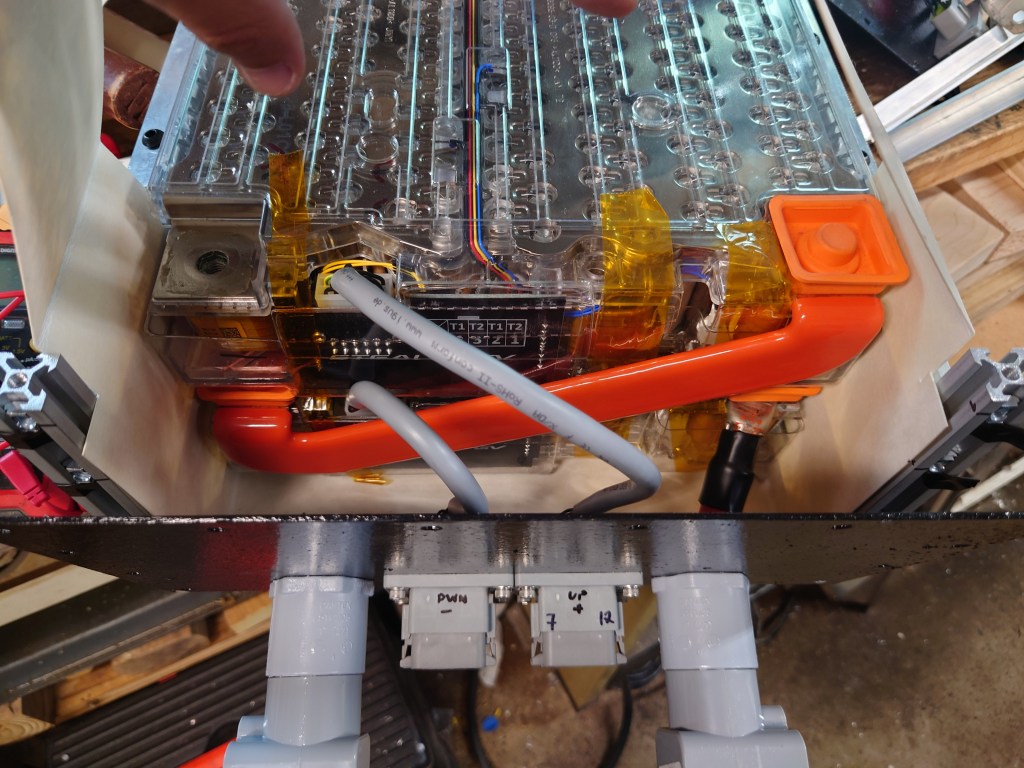
While constructing them, I installed Stealth EV’s BMS cell-tap boards, and was pleased with how easy they were to install. Everything snapped together, and I re-used Tesla’s plastic rivets. From there, I connected two 12-wire cables to route the BMS connector to the outside of the battery pack. Additionally, and most difficult, was the traction pack cable. They took up a lot of space, and were physically difficult to maneuver. I picked up low-profile battery jumper from Stealth EV to connect the modules within each of my 3 packs.
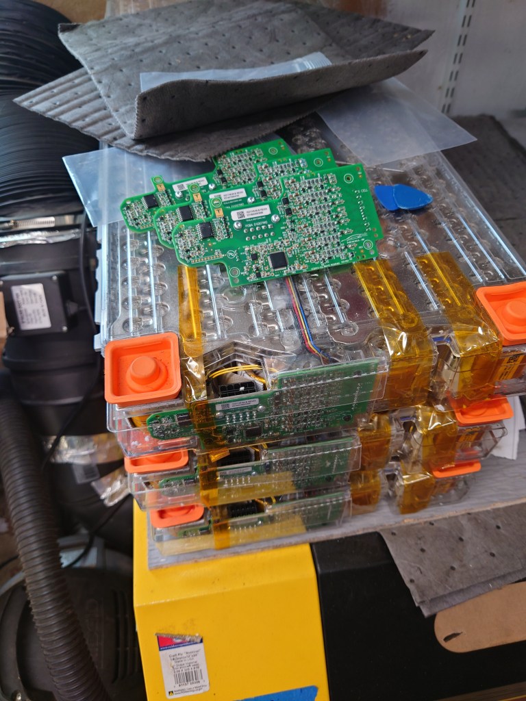
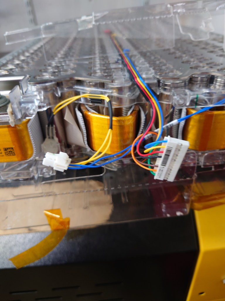

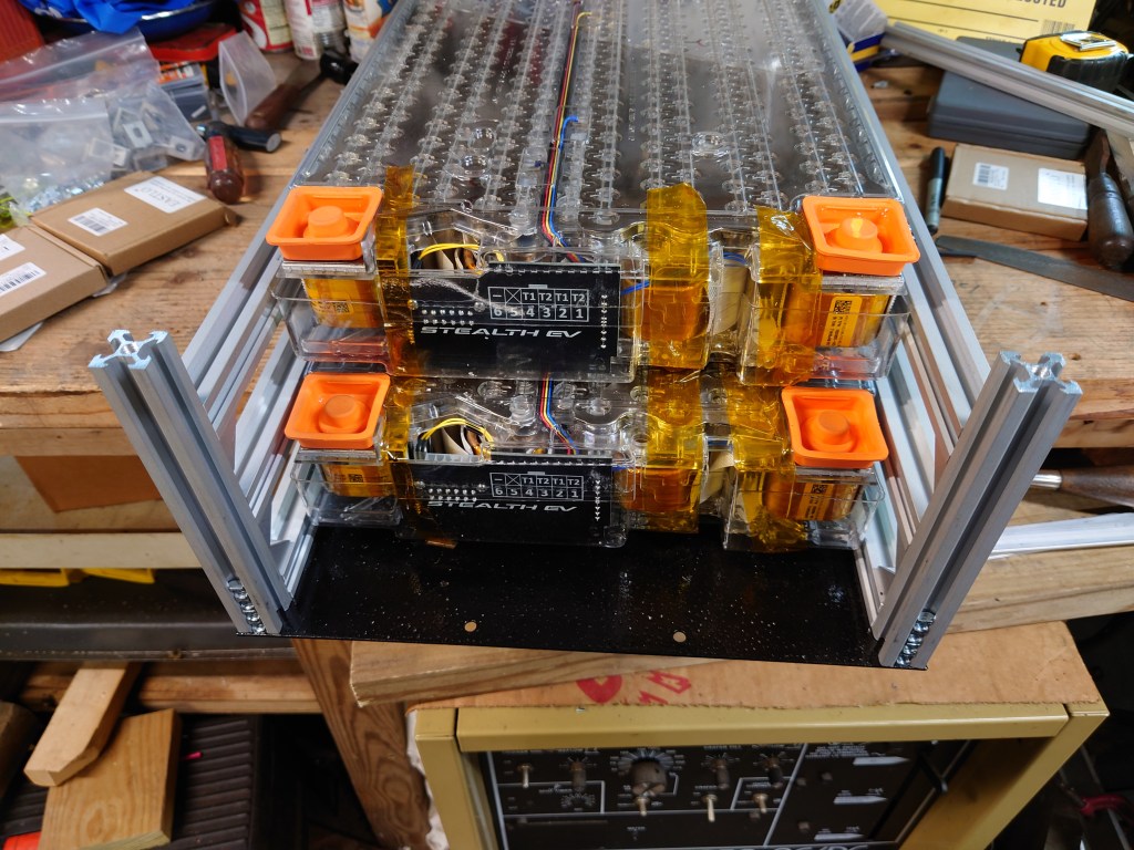
Each battery pack contains 2 tesla modules, with access points for the BMS/thermistor connector of each module, the pack positive and negative terminals, and the water cooling system. They stayed in this state over the winter until I was able to roll the car outside to prepare the frame for installation.

Frame preparation.
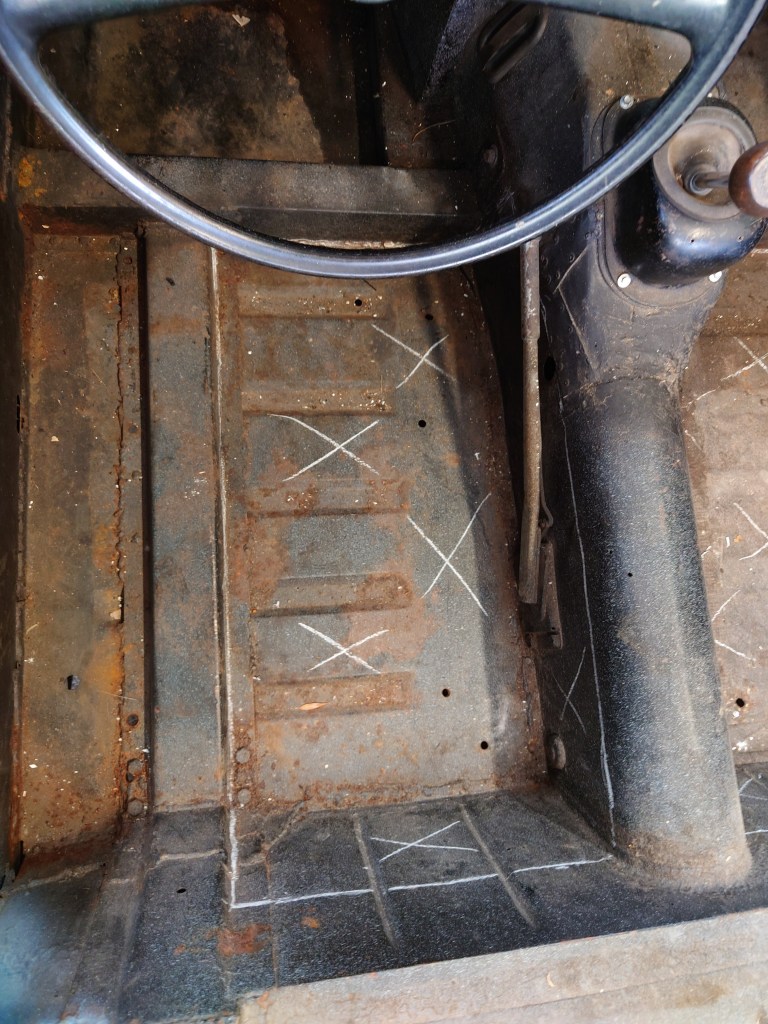
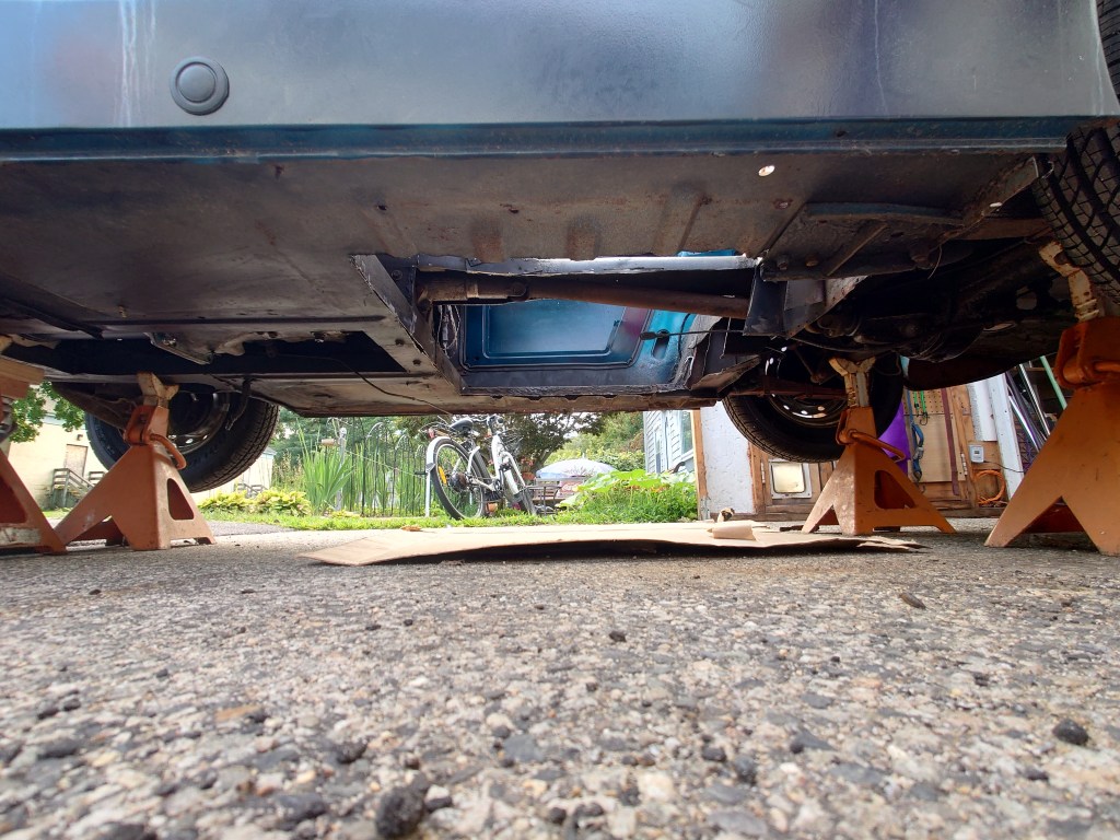
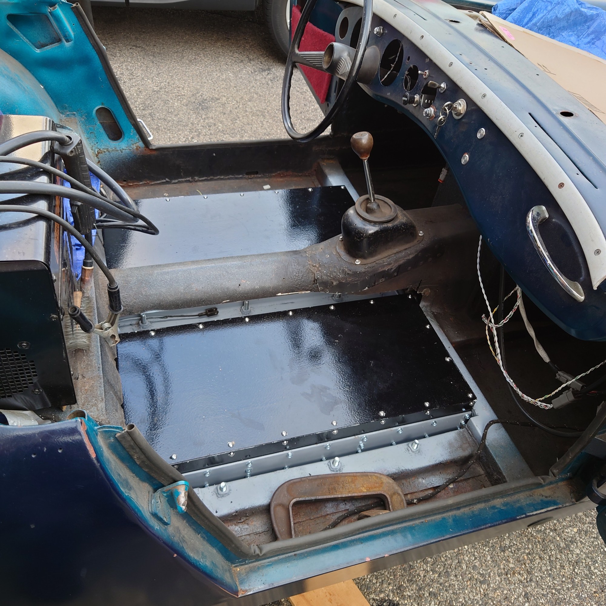
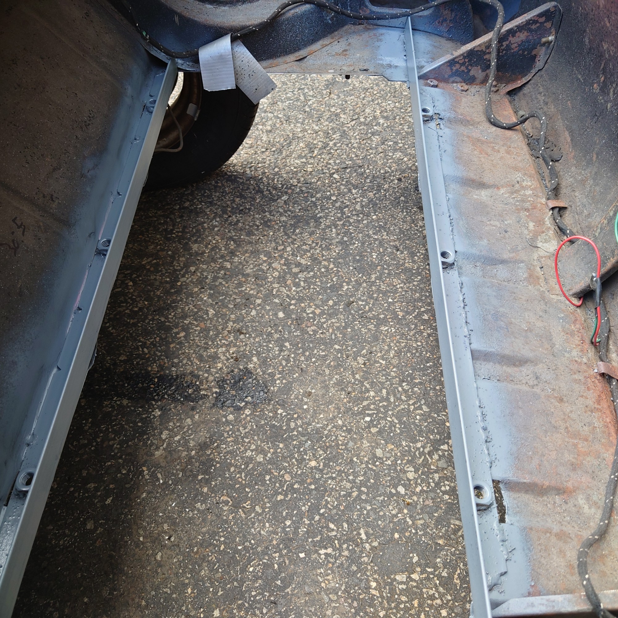
My plan was to install the three battery packs with one under the driver, one under the passenger, and one where the gas tank used to be. And so I started cutting and grinding and marking and double-checking and grinding some more. One of the unintended side effects of trying to take up the whole floor space in the midsection was that I found the floor was not truly connected to the support beams that run the length of the car. I had to weld the seam that I created.


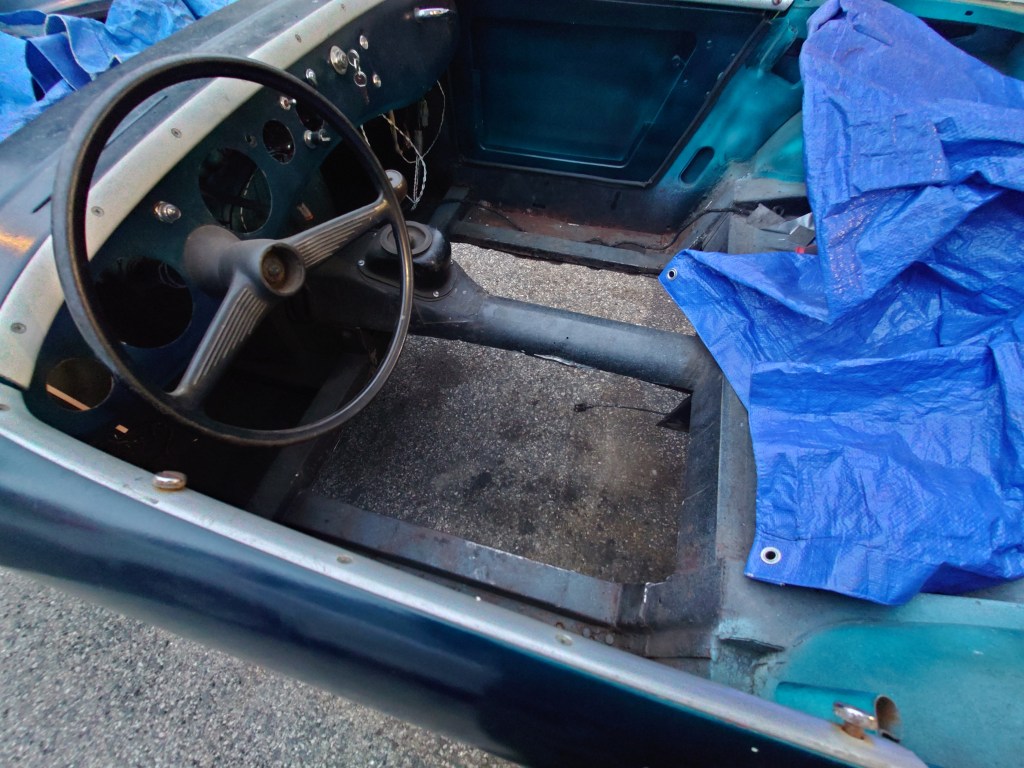
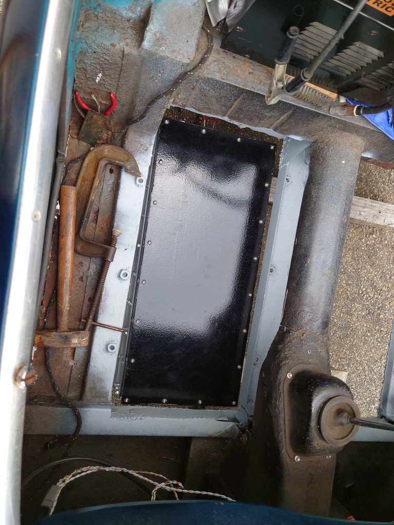
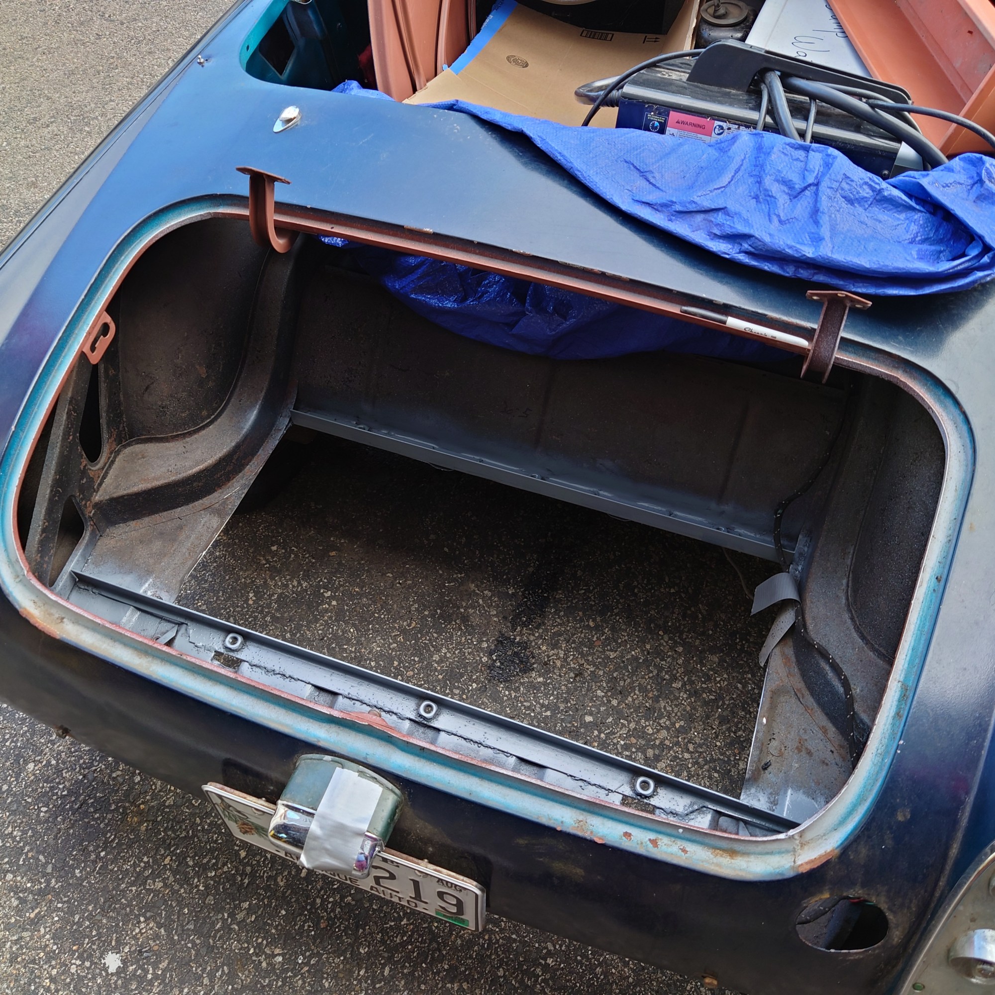
To support the packs side-by-side in the middle of the car, I fabricated a truss that would sit in the center of the vehicle. It’s a little overkill, but I’d rather a support be stronger than needed than weaker. To affix the batteries I welded some weld-nuts to the support rails and truss that I installed, and the same thing in the trunk with two large L-brackets to distribute the weight. After all this, the frame was ready for the batteries to be installed. (It looks like I didn’t take pictures of just the truss, so here it is installed, and the weld-nuts on the existing frame rails)

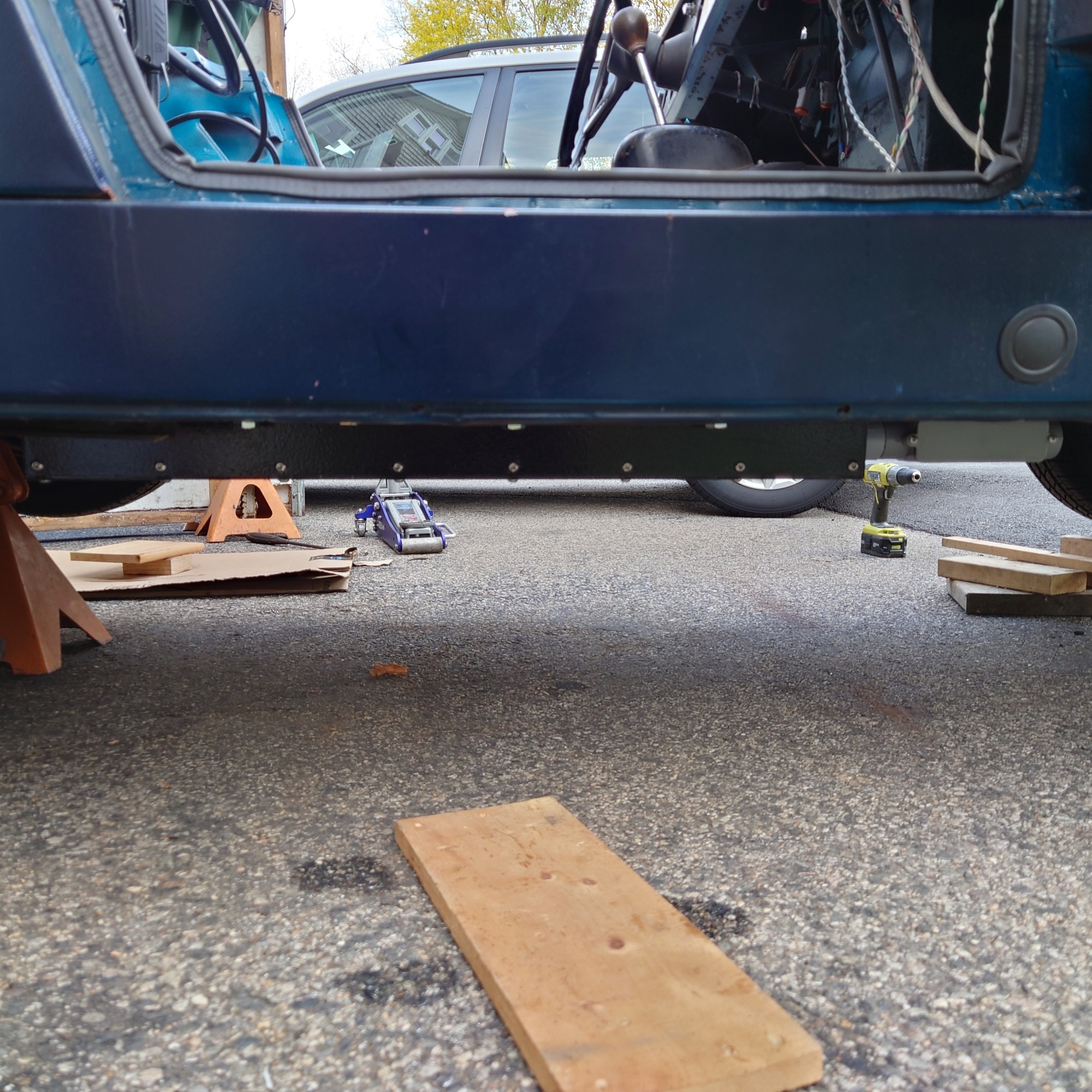
Installation.
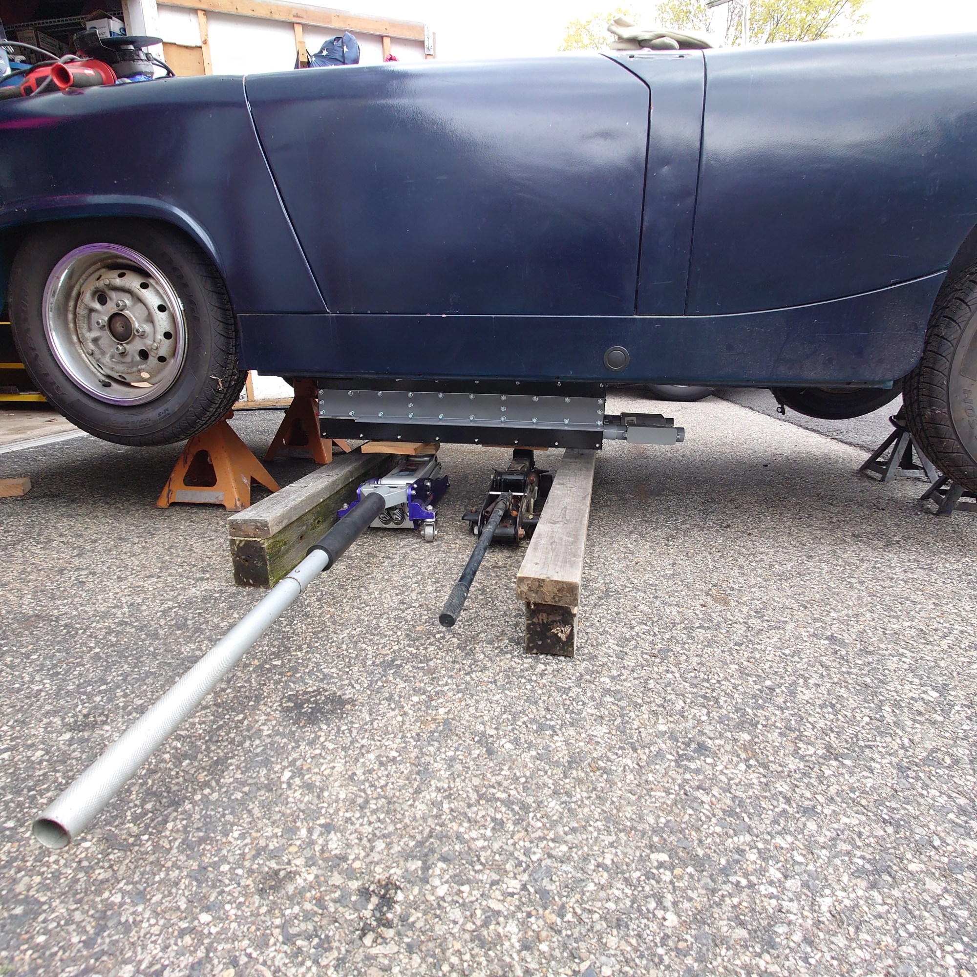
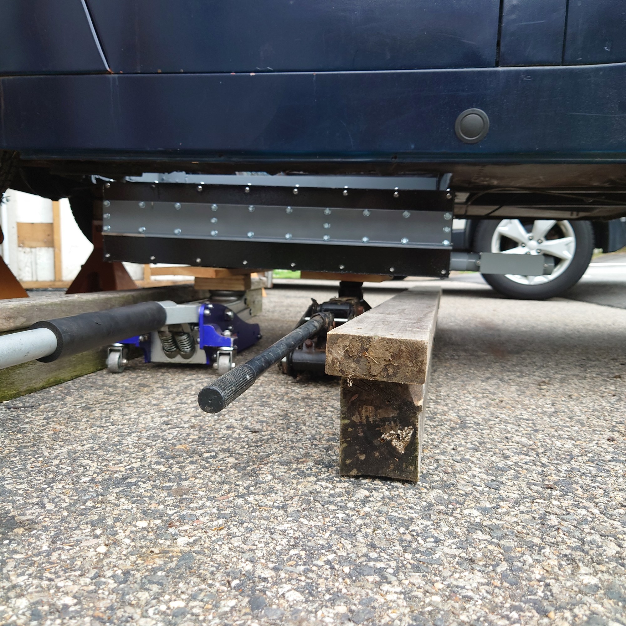
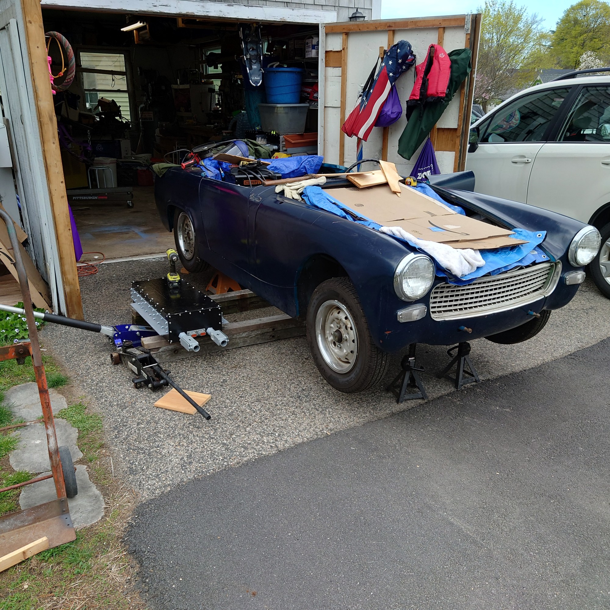
In order to save my back which had only recently recovered from some issues I was having, I utilized an engine hoist and strapping to lower the batteries onto a dolly, to be brought over to the car. From there, the batteries were transferred to two beams and slid to approximately the right location underneath the car. I lifted the batteries with a small jack, took the location that it would be in, and drilled holes on-location. I knew that this would have to be job-work, rather than to-plan. I repeated this 3 times and installed all the batteries in place with ½-13 bolts. Lifting the batteries was the most difficult part, as finding the balance point was guess-and-check. Pry bars and repeated attempts were necessary. However, everything fit and was snugly attached to the Sprite at the end. Yippee!

Running the HV wires and BMS.
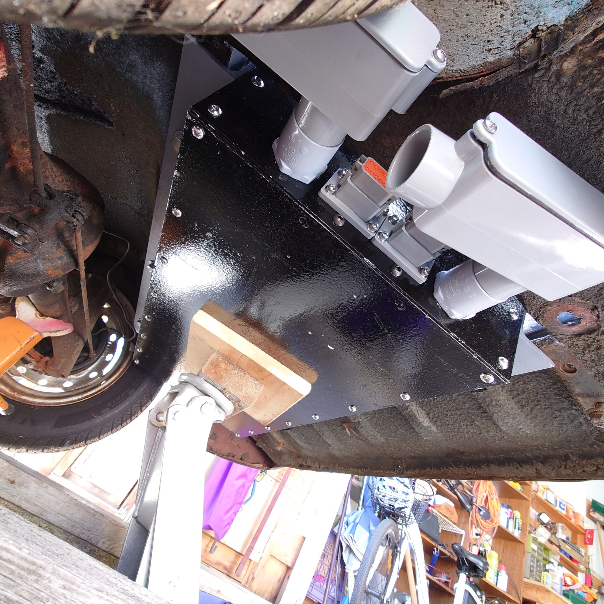
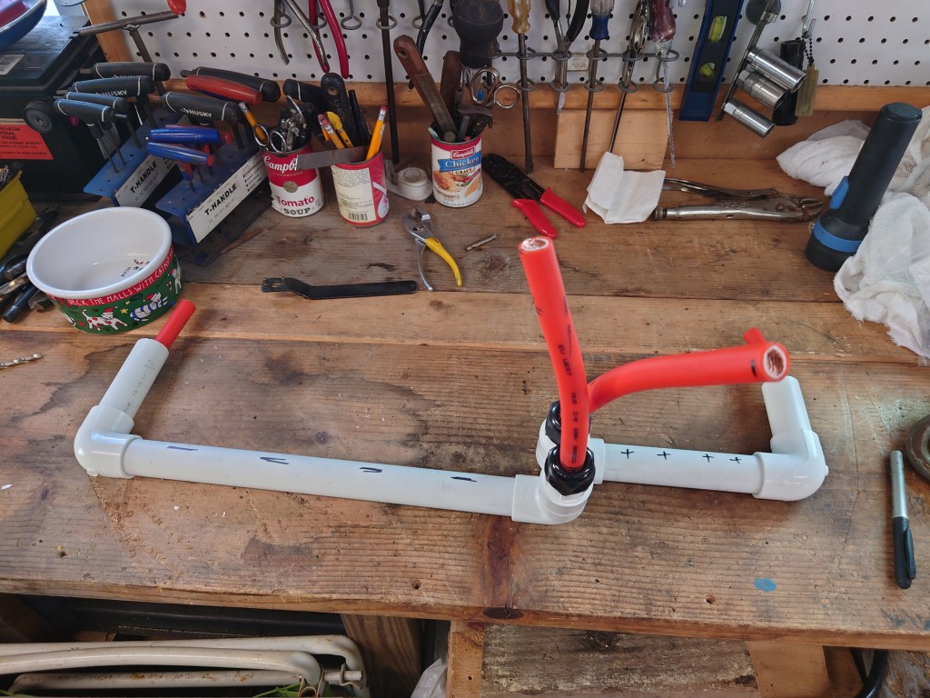
After the batteries were installed, I needed to run the high voltage traction pack cable from and to each pack and to the front of the vehicle where the contactor box is. I wanted to protect as much of the cable a possible from damage, so I sheathed it in PVC conduit (pipe). I’ll have to color it orange before I use it on the road, but I’m pleased with how it fits underneath the car. One unintended development with the batteries to note is that the car is riding almost on top of its rear suspension. There’s about an inch of throw before the bumpers on the rear struts bottom out. I’m going to have to figure that out.

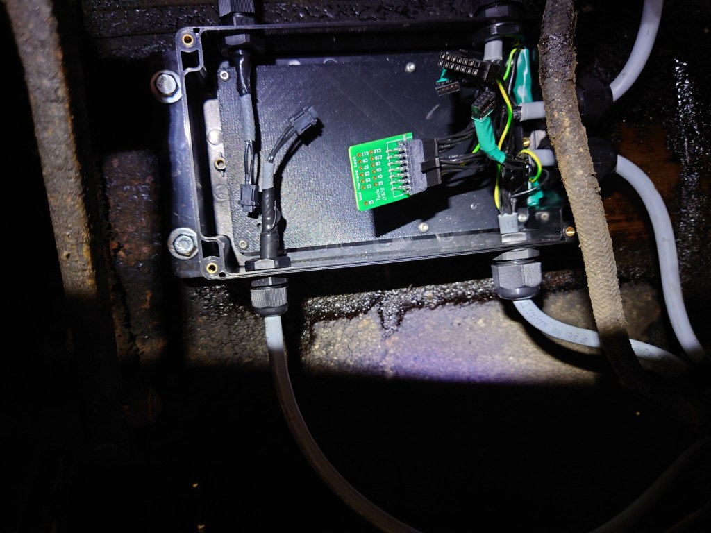
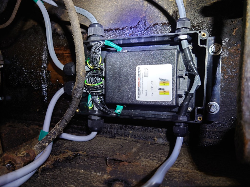
For the BMS I utilized the ThunderstruckEV BMSS with 24 positions for cells, paired with a MCU in the junction box at the front of the vehicle. I verified that each of the cables I made were correctly wired to each cell before routing them into the BMSs themselves. The BMSs are located underneath the car in the space that is made for the axle. I don’t expect them to be damaged in this location.

Ready for the first charge?
It’s been a long and tough journey. While I’ve been working this project I earned a Master of Science in Robotics Engineering, and was licensed as a Professional Engineer. Both of those things took huge amounts of time that I could have been working on the car. Additionally, I’ve gotten into road racing way more than I have in the past, and so there go a lot of my weekends too. This project has taken a long time to get to the place it has, but I feel as if things are going to go much faster in the coming months, I’ve got big plans!
