Cable Driven Parallel Robots (CDPR) are lightweight, versatile, and have benefits that let them compete with gantry style and serial-arm manipulators. A CDPR is a mechanism with an end effector that is oriented and translated through tensioning flexible cables, rather than rotating solid links of a classic industrial robotic arm. Because CDPRs do not have bulky links, they can move the end effector rapidly to positions within the workspace. Moreover, they are relatively simple to manufacture, have a wide workspace, and may be taken down and reconfigured for different locations.
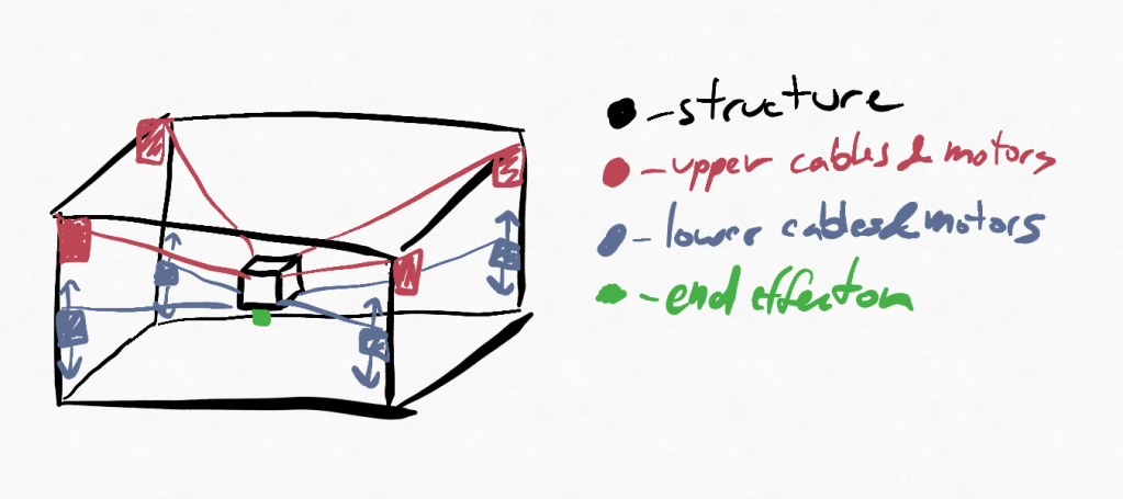
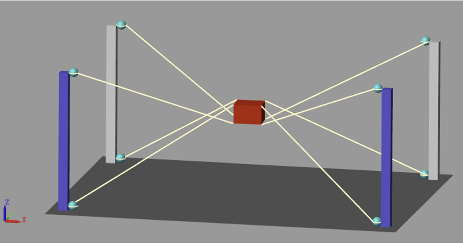
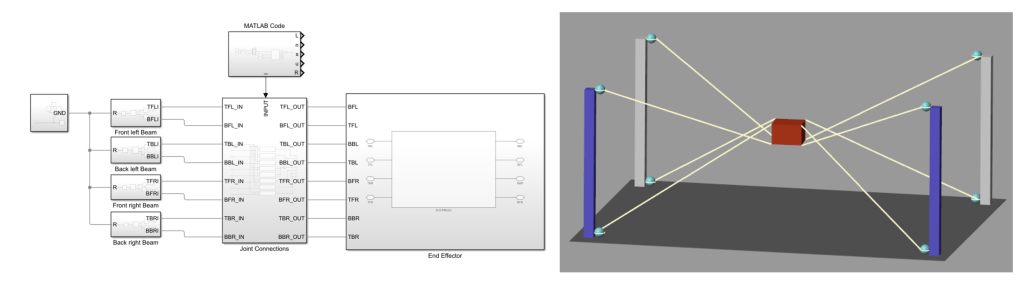
During my graduate studies in the class RBE521 – Legged Robotics, me and a partner developed a simulated CDPR with the intent of using it for 3d printing buildings as its notional context. Previous work by researchers in this field had proven quite productive, and so we decided to try develop and test a CDPR in Matlab using Simulink and Simscape. In the sketch above, one can see that the system under evaluation was of a rigid rectangular prism with 8 driven cables and a centrally located end-effector. The screenshot below (featured as the headline photo) shows the final implementation. On the left is the diagram showing the connections and driven effectors, and the right shows the simulated output.
One of the greatest benefits of CDPRs is that their inverse kinematics are easy to compute, which means that given a motion profile and an understanding that the intended motion is within the workspace of the robot, the solution is closed form. Using a pose, P, composed of a vector O representing the location of the end effector (EE) and 3 Euler angles, one can use geometric data from the CDPR configuration to directly calculate the cable vectors. Refer to the sketch below, with the following variables:
O_i = pose (P) in 6 degrees of freedom (position, orientation)
l_i = length of 'leg' i (also cable)
S_i = connection geometry of end-effector
U_i = connection geometry of frame. 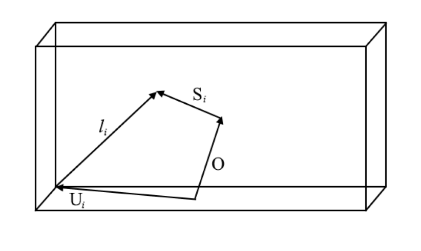
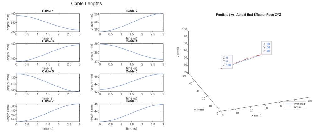
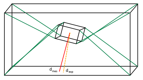
And finally, one of the most interesting parts of this project was trying to develop a calibration schema. One method that researchers have used is attaching a laser to the end effector, and then taking a sample of measurements over the workspace with high observability (relatively great leg/cable displacements) and then using a non-linear least squares fit algorithm to determine the best matched parameters for the CDPR, as there are always going to be manufacturing inconsistencies. This simulation was unable to replicate the success of previous researchers, and that is believed to be due to the rotation of the end-effector. Specifically, rotation about the vertical z-axis (yaw) causes displacement in the cables , which is not sensed by the laser pointing through the z-axis. As such, there is a great deal of ambiguity in position generated by yaw of the end-effector. However, it can be theorized that if one or more points for calibration are added to the end effector, rather than a single-dimensional linear measurement from a laser, that the calibration parameters could be accurately fit using numerical methods. See the picture below for the setup.
If you’d like to see the full report generated, refer to the PDF below.
