
The AR4-MK3 is a well-featured open-plan 6 DOF arm designed by Chris Annin of Annin robotics. Annin Robotics – open source 6 axis robots you can build yourself The AR4-MK3 is used as a teaching aid, research platform, and general hobbyist robotic arm. This blog post dives into what it took to assemble the robot arm.
On arrival I inventoried the pieces and parts to ensure that I had what seemed like everything. I decided to order all the pieces instead of 3d printing or trying to build myself, because as I’ve gotten older, I’ve realized that my time is often more valuable than the money I spend on things. More on that some other time…
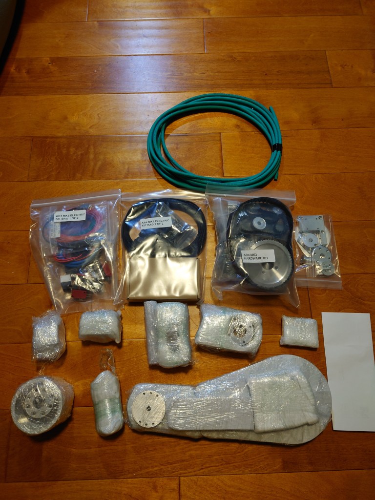
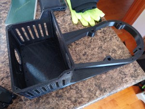
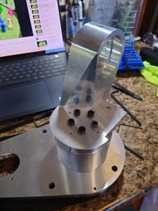
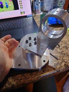
There were however some pieces that are required to be 3d printed, such as the base enclosure, some guards, and mounts for the homing switches. The initial assembly (up to joint 4) went rather quickly. The angular contact bearings with preload were a welcome solution to the variation in loading that inevitably comes from robot arms. I was also pleased with the low backlash from many of the joints. It was not imperceptible though, and of particular note is the backlash on J2.

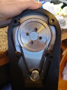
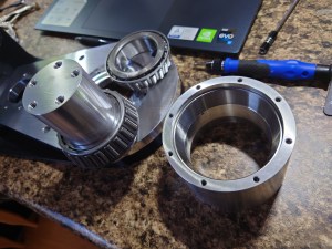

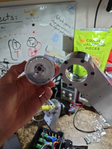
This is of great concern, because backlash closer to the root of the robot arm magnifies itself through the other joints. It’s a simple angular deviation problem, where a degree off an inch out doesn’t make a perceptible difference. However, a degree off a foot out, you’re almost at an ⅛” deviation. Given the time, I would invest some research into solving the J2 issue. Cycloidal drives are, I believe, industry standard for this problem. With a bit of thinking, some clever machining (hopefully at scale for reduced per-unit cost), a much better J2 gearbox could be made. Perhaps I can make a prototype when I finish my DM2000 conversion!


I deviated from C. Annin’s instructions, because I saved routing all the wires into the enclosure until the end. Something didn’t sit right with me thinking about plugging and unplugging the connections as I routed each joint’s power, encoder, and limit into the electronics box. This proved to pay off (at least to me) because I got everything crammed into the tight space. Certainly not the prettiest wiring job, but it gets me off the ground and into running the arm.
Initial tests with the arm proved satisfactory. I broke the J3 homing switch, due to not following the configuration procedure properly, but I replaced the switch and moved on with commissioning. My ultimate goal with this is to switch to ROS-2 to run the arm, and this way I can develop my ROS skills, while working on a cool piece of equipment. I’m currently at the commissioning stage for ROS, and have already noticed that the calibration feature is not fully featured for ROS. This will take some time ensuring that each joint is driving in the correct direction, and the link to the encoder matches. Additionally, that each limit switch is putting the link in its homed state. Below is a picture of the initial ROS package in RVIZ working. I’m using WSLg with ROS-2 Rolling (not currently supported, but that’s part of the fun).

