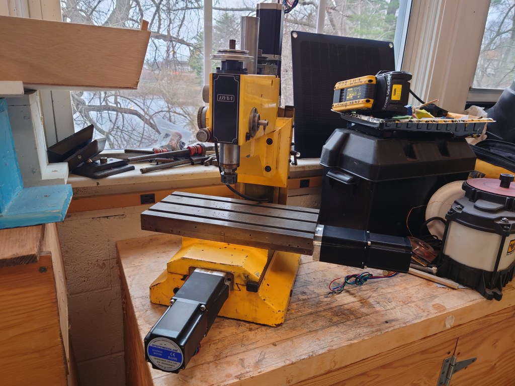
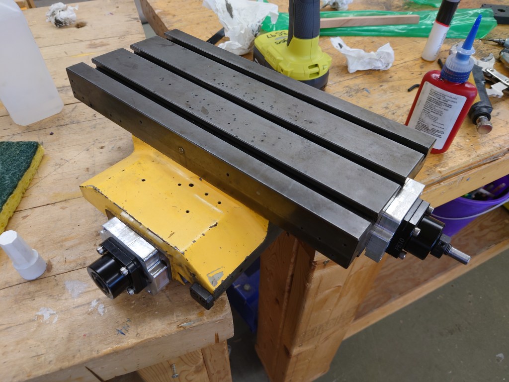
The first update for this project is that I’ve got my linear motion system figured out, and have moved forward with assembling all the constituent parts. The mini mill is now in a state where I can start thinking more about the limit switches, motor control, and power. But before all that, I can break the mechanical system into a few parts, namely the ballnut mount, the ballscrew, the motor and bearing block mount, and finally the stepper motor that will drive the axis. I have three of these systems for XYZ motion with an up-rated stepper for the vertical Z-axis. I’ll detail my implementation below.

Ballnut Mount
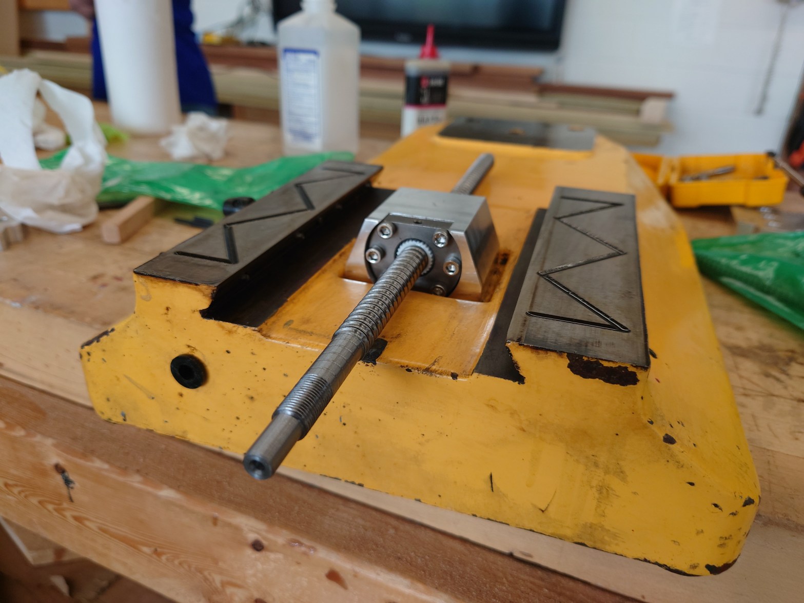
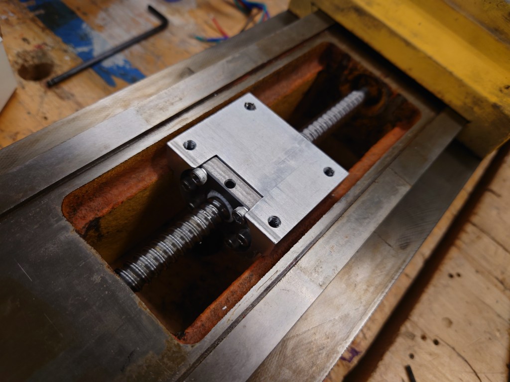
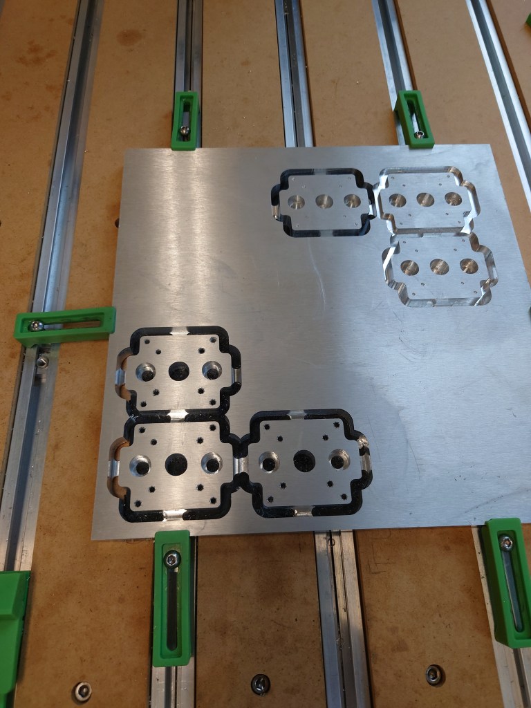
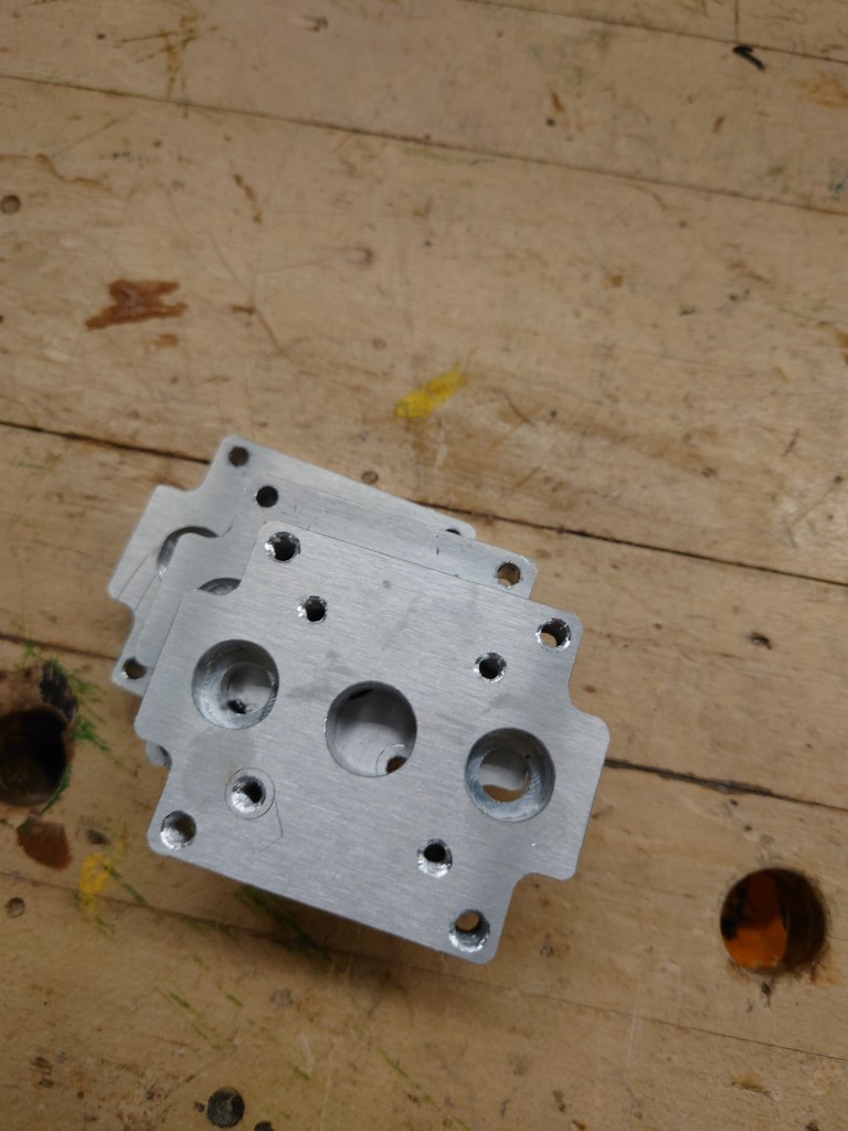
I went through 3 or 4 iterations of 3d-printed mounts checking that they fit in place and were oriented correctly before finally purchasing milled out pieces. I’m very happy with how they came out, and that they fit together with the ballnut. This is a huge improvement over my previous conversion, which ended up using a 3d-printed mount to run all the motion components. It’s kind of a shame that I didn’t mill out the pieces myself, and instead used Xometry to contract out what I needed, but at the same time I didn’t have the necessary tools to make the pieces. That’s part of what doing this conversion is about in the first place!

Ballscrew
I chose SFU1204 ballscrews, nominal diameter 12mm with 4mm pitch, for the physical part of the motion. These can be found cheaply on Amazon and eBay in the ‘rolled’ form. These screws are so cheap because they go through a deformation process, which squeezes the material into the right shape, rather than a grinding process which removes material. The grinding process takes much longer, but the process is much more precise. For the lengths of travel and my intended hobbyist use case, justifying ground ballscrews as opposed to rolled would be hard. The 12mm size was decided on because the next size up, 16mm, would not fit with the appropriate ballnut. The 16mm screw would fit, but the nut that makes all the motion happen would not.


One interesting thing is that during assembly for the Z-axis I had to remove the ballnut to fit the screw into the frame. I was very hesitant at first to learn how to repack a ballnut, but after taking it apart and looking at the internals, I got the hang of the recirculating races and was able to use a small pick to place the ball bearings in their proper locations. Great success, and I learned something new!
Motor and Bearing Block Mount
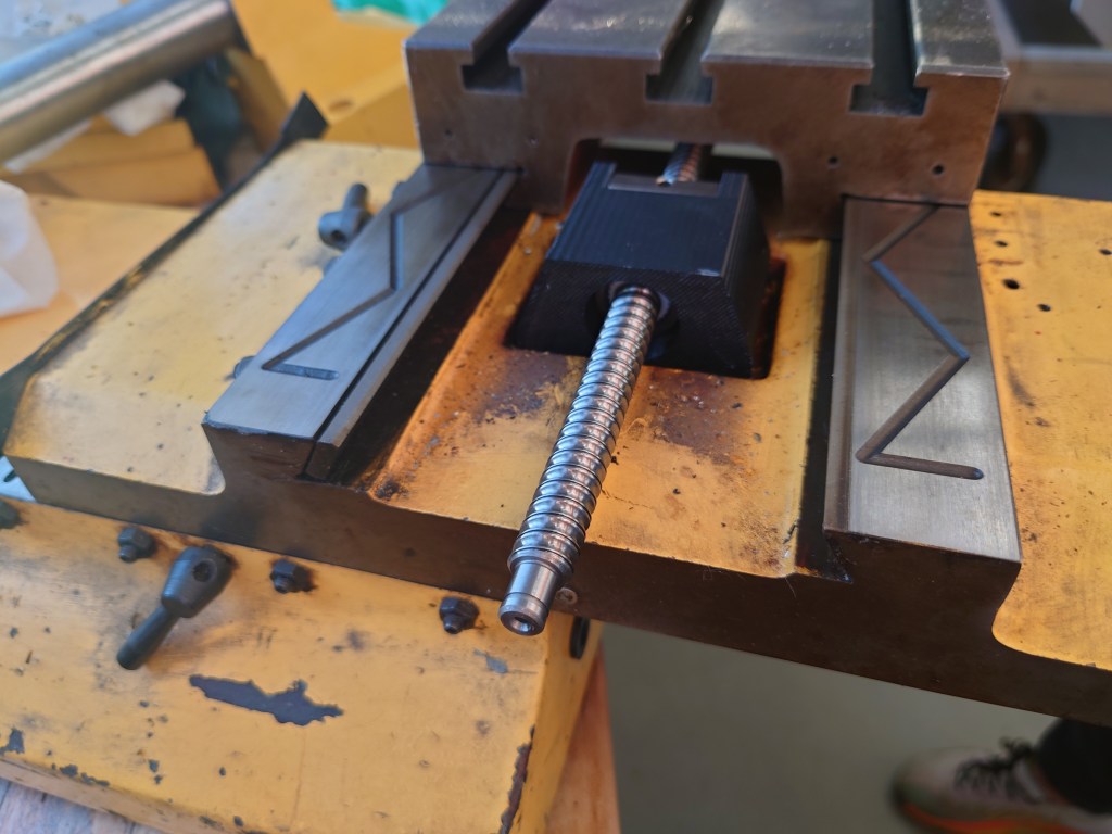
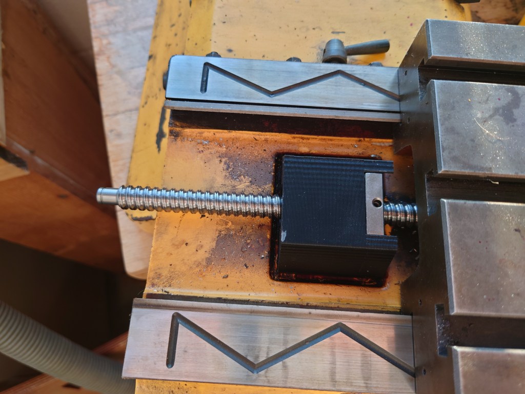
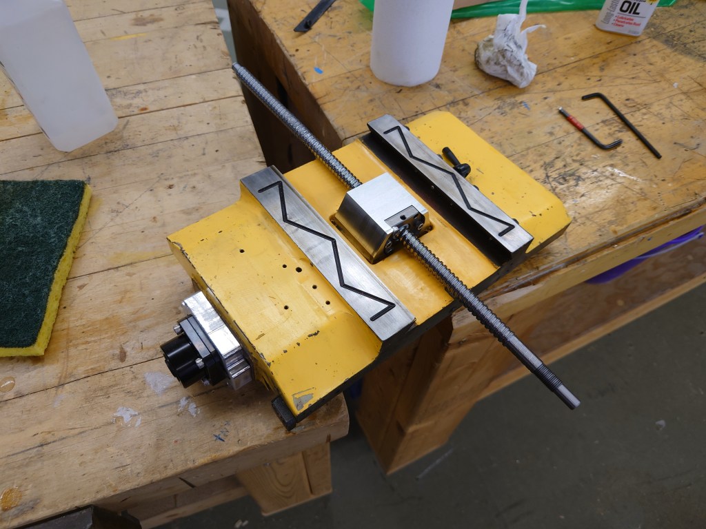
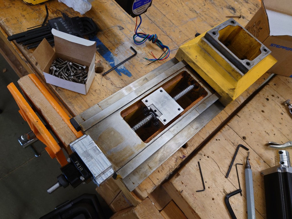
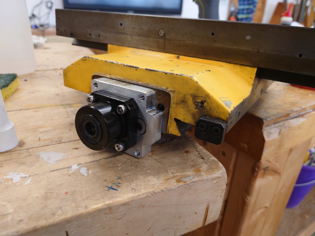
The motor and bearing block mount replaces the original mount using the original hardware. The mount first gets affixed to the slide, and then the fixed bearing mount that handles the rotational and thrust loads on the screw is mounted. Through that the end of the ballscrew is fed, and a nut clamps the ballscrew in place within the bearing block. I milled these out on a Shapeoko 5, because the design is rather simple.


Stepper Motor
The stepper motor is a standard Nema23, which will be stepped off a motor driver at 36V. The motor is coupled to the end of the SFU1204 ballscrew with a flexible aluminum coupler. The motor is affixed to the motor and bearing block mount with a large 3d-printed housing which occludes the fixed bearing block, and makes tightening the coupler set-screws a chore. Overall though it makes for a solid unit and a clean look that keeps debris out of all the rotating parts.